

Thuc notes - OS Kernel Assembly
- First part of the kernel. Will be called by the bootloader.
- Define a mechanism that the bootloader can recognize and load the system kernel.
- It implements the logic that can’t handle from a high-level kernel.
- Basic functions:
- Define a function
_startthat will be jumped to from bootloader as an entry-point. - Responsible to allocate stack to use.
- Transfer to the high-level kernel by calling to function written by C, C++, Go, Rust etc.
- Keep the computer in an infinite loop.
- Define a function
1. Multiboot standard layout
- An interface standard that’s used by the bootloader to recognize and load the system kernel.
- Bootloader will search multiboot headers (magic numbers) to recognize the kernel as multiboot compatible.
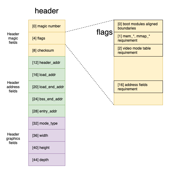
| Offset | Type | Field |
|---|---|---|
| 0 | unsigned 32-bit | magic number |
| 4 | unsigned 32-bit | flags |
| 8 | unsigned 32-bit | checksum |
| 12 | unsigned 32-bit | header_addr |
| 16 | unsigned 32-bit | load_addr |
| 20 | unsigned 32-bit | load_end_addr |
| 24 | unsigned 32-bit | bss_end_addr |
| 28 | unsigned 32-bit | entry_addr |
| 32 | unsigned 32-bit | mode_type |
| 36 | unsigned 32-bit | width |
| 40 | unsigned 32-bit | height |
| 44 | unsigned 32-bit | depth |
- Include: magic number, flags and checksum
Magic number
- The hexadecimal value always is 0x1BADB002
Flags:
- Control address fields and graphics fields.
- Bits 0-15 is a required feature. If the boot loader can’t understand the flag or fulfil them, it fails to load the OS image.
- Bits 16-31 is optional features. If the boot loader can’t understand the flag or can’t fulfil them, it’s ignored.
| Bit | Description |
|---|---|
| 0 | If it’s set, all boot modules loaded with must be aligned on 4KB page boundaries |
| 1 | If it’s set, mem_lower and mem_upper in multiboot information structure, that’s passed by the boot loader to OS, must be included. mmap_length and mmap_addr are had in case the boot loader can pass it to. |
| 2 | If it’s set, information about video mode table must be available in multiboot information structure, the boot loader passes that to OS, must be included |
| 16 | If it’s set, header address fields are used by boot loader instead of the fields in the actual executable header. Don’t need to provide if the kernel image is in ELF format, required if it’s a.out format or in some other format |
checksum:
- Value’s always
-(magic number + flags)
- All of the address fields enabled by flag bit 16 are physical addresses.
- Include: header_addr, load_addr, load_end_addr, bss_end_addr and entry_addr
- header_addr: the physical address of the beginning of the multiboot header.
- load_addr: the physical address of the beginning of text segment.
- load_end_addr: the physical address of the end of the data segment. So the text and data segment are consecutive in the OS image.
- bss_end_addr: the physical address of the end of the BSS segment.
- entry_addr: the physical address to jump to start OS from the boot loader.
- All of the graphics fields are enabled by flag bit 2.
- Include: mode_type, width, height and depth
- Specify the preferred graphics mode
- Recommended mode by OS image, the boot loader may choose a different mode if it sees fit.
- mode_type: 0 = linear graphics mode, 1 = EGA-standard text mode
- width: The number of columns
- height: The number of the lines
- depth: The number of bits per pixel in a graphics mode, zero in a text mode.
1.2. Stack definition
- Create a section; allocate 16 Kb; create a symbol at the top by setting the esp register. The stack grows downwards on x86.
- Aligned 16-byte according to the System V ABI standard and de-facto extensions
1.3. Infinite loop
- Disable CLI interrupts
- Use
hltto wait for the next interrupt to archive. - Jump back to the waiting step for
hltagain if the computer wakes up by any interrupting.
1.4. Multiboot information structure
- Multiboot information structure is data that the boot loader communicates to the OS.
- The EBX register contains the physical address of the multiboot information structure.
| Offset | Size | Field | Description |
|---|---|---|---|
| 0 | 4 | flags | |
| 4 | 4 | mem_lower | Memory definition |
| 8 | 4 | mem_upper | Memory definition |
| 12 | 4 | boot_device | Boot device information |
| 16 | 4 | cmdline | Command line information |
| 20 | 4 | mods_count | Loadded modules |
| 24 | 4 | mods_addr | Loadded modules |
| 28-40 | 16 | syms | Detail fields between those addresses are controlled by the flag |
| 44 | 4 | mmap_length | Memory map |
| 48 | 4 | mmap_length | Memory map |
| 52 | 4 | drives_length | Drives |
| 56 | 4 | drives_addr | Drives |
| 60 | 4 | config_table | Config table |
| 64 | 4 | boot_loader_name | Boot loader name |
| 68 | 4 | apm_table | Advanced Power Management table |
| 72 | 16 (2 for each) | vbe_* | |
| 88 | 21 | framebuffer_* | framebuffer |
Flags:
- Indicates features are defined in the following fields will be used.
| Bit | Description |
|---|---|
| 0 | Enable mem_lower and mem_upper fields to control memory boundary |
| 1 | Enable to set the boot_device fields |
| 2 | Enable to set the cmdline fields |
| 3 | Enable to set the modules fields |
| 4 | Defile structure offset 28-40. 4 or 5 is set, another is unset. |
| 6 | Enable to set the memory map fields |
| 7 | Enable to set the drives fields |
| 8 | Enable to set the config table field |
| 9 | Enable to set the boot loader name field |
| 10 | Enable to set the Advanced Power Management table fields |
| 11 | Enable to set the VBE fields |
| 12 | Enable to set the framebuffer fields |
Memory:
mem_lower, mem_upper.- Define total available memory that can use.
Boot device:
boot_device.- Indicate boot device which BIOSK disk device the boot loader loaded the OS image from
- If the OS is not booted by BIOSK disk, it should be clear.
Command line:
cmdline, byte offset = 16, size = 4.- Define the physical address of the command line that is passed to the kernel.
Modules:
mods_count, mods_addr.- Indicate what boot modules were loaded along with the kernel image.
mods_count= number of modules loaded.mods_addr= physical address of the first module.- Each module will have the following structure
| Offset | Size | Field | Description |
|---|---|---|---|
| 0 | 4 | mod_start | physical starting address of module |
| 4 | 4 | mod_end | physical ending address of module |
| 8 | 4 | mod_end | arbitrary string of module. It can be command line, pathname |
| 12 | 4 | reserved | set 0 by the boot loader and ignored by OS |
Symbol table:
- If bit 4 of the flag are set, the following symbol location info is used
| Offset | Size | Field | Description |
|---|---|---|---|
| 28 | 4 | tabsize | size parameter |
| 32 | 4 | strsize | size parameter |
| 36 | 4 | addr | physical address of and array of a.out format nlist structures |
| 40 | 4 | reserved | just for reversed |
- If bit 5 of the flag are set, the following s section header table from ELF info is used
| Offset | Size | Field | Description |
|---|---|---|---|
| 28 | 4 | num | number of entries |
| 32 | 4 | size | size of each entry |
| 36 | 4 | addr | Physical address fields of the ELF section header |
| 40 | 4 | shndx |
Memory map:
mmap_length, mmap_addr- Indicate a buffer containing a memory map starting address and its length. BIOS provides the buffer having a memory map. The map provided is guaranteed to list all standard RAM that should be available for usage.
- Each item in the memory map has structure:
| Offset | Size | Field | Description |
|---|---|---|---|
| -4 | 4 | size | size of memory map item |
| 0 | 8 | base_addr | physical address of the memory that the map define to |
| 8 | 8 | length | the size of the memory region |
| 16 | 8 | type | the variety of address range represented. 1 = available RAM, 3 = usable memory holding ACPI information, 4 = reserved memory which needs to be preserved on hibernation, 5 = occupied by defective RAM modules and all other values currently indicated a reserved area |
Drives:
drives_length, drives_addr- Indicate the address of the physical address of the first drive structure and the size of drive structures.
Config table:
config_table- Indicates the address of the ROM configuration table returned by the
GET CONFIGURATION BIOScall
Boot loader name:
boot_loader_name- Contains the physical address of the name of a boot loader booting the kernel
Advanced Power Management table:
apm_table- Contains the physical address of an Advanced Power Management table.
VBE
- All fields starts with
vbe_ - Indicate fields of VESA BIOS extensions.
Graphics
- All fields starts with
framebuffer_ - Indicate fields of framebuffer table.
2. Multiboot2 standard layout
- TBD.
- Magic number: 0xE85250D6